
This document is about geting the Gerber & Excellon Files needed to use in flatcam to generate the gcode files formilling PCB milling in 3018 CNC with Candle or GRBL-control.
We should use the LabeE.dru file that is available on the link bellow.
LabE – eagle – design rules (dru) and library (lbr)
These design rules are made to assure that the PCB board are acceptable to be made in a cnc machine.
In the schematic and the board view the grid should be 0.01 in (0.254 mm), that is the std measure of a dil package and common discrete components

First we design the schematic of our circuit, and validate it.

Secondly we design the board.

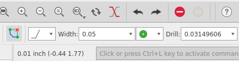
When doing the PCB tracks we need to use 0.05 in, (1.27 mm) for with, and 0.03149606 in, (0.8 mm) for drill.
After we complete the board layout we should validate it with de rules defined in LabE.dru.

After design the schematic and the board layout to make in a CNC 3018 we need to generate the PCB Gerber file for tracks layout and the Excellon file for drill layout.
Click on File > CAM processor, and it the CAM processor dialog box should open. Click in Bottom Cooper to see the circuit.

If we click in the gerber folder we may see that the output is Gerber RS 274X.
Check if the units are ok for your job. The flatcam need to be configured to use the same units.
For generate the gerber &Excellon files to feed the flatcam software we dont need to change anything for using.
But it better to mirror the Bottom Copper layer, and the drill layer, because the PCB was draw from upper view, and will be milled from bellow.
To mirror the Bottom Copper layer, select it, click in advanced, and select for instance the horizontal mirror.
To mirror the Auto Drill layer click in advanced, and select for instance the horizontal mirror.
If we mirror the layers, in the flat cam they will be also mirrored, and them we need to placed (moved) above 0,0 coordinates.
We need to remember to place place the cooper plate for milling as we specify here.
To export the gerber files, we only need to click on Process job.
But we may use the Export as zip, and the Export to project directory options.
If we don’t check the Export to project directory option we need to select the destination folder.

Then we can save the CAM job for later use, or discard it by cancel.
After the Process job was complete, and we saved, or cancel the CAM job file saving, we will have an new directory called CamOutputs, with 3 folders inside.
- Assembly
- DrillFiles
- GerberFiles
The GerberFiles have at least one of the required files. The copper_bottom.gbr. This file have the circuit layout and we will use it in flatcam.
The DrillFiles have the drill_1_16.xln that is drill layout file. We also use this file in flatcam.
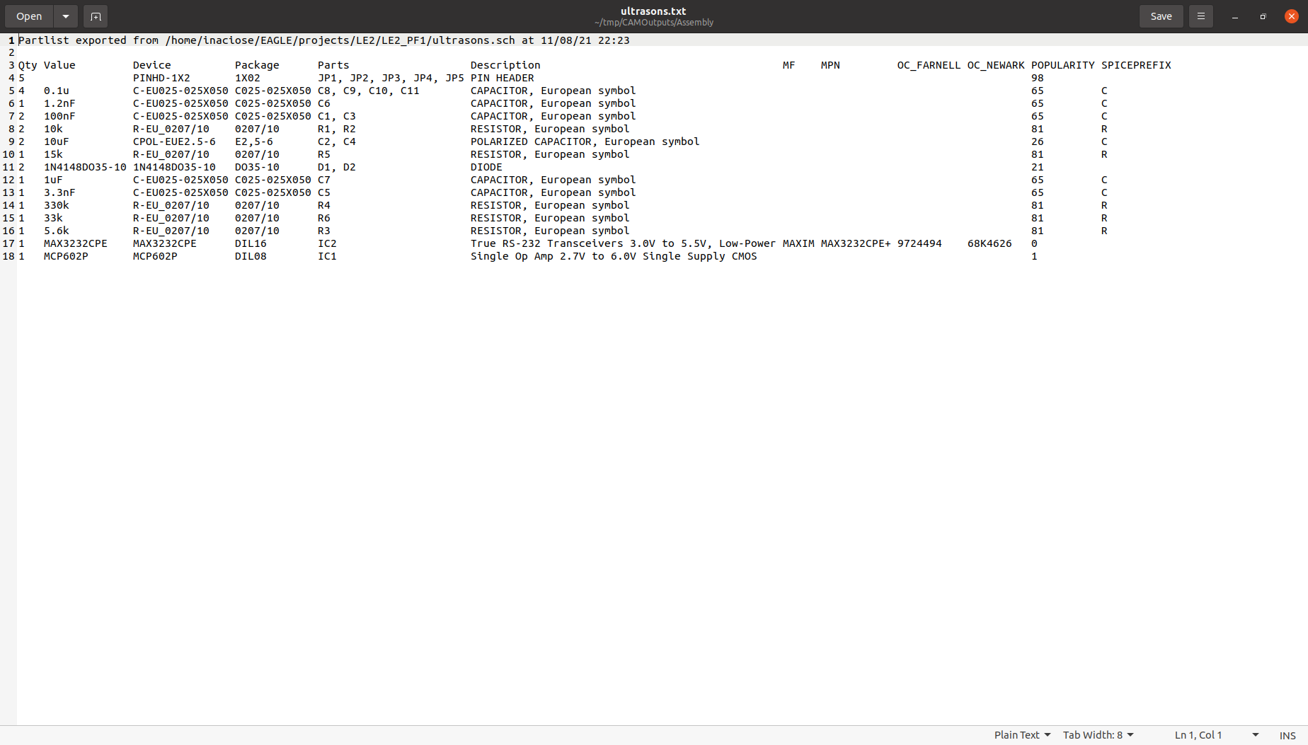
The assembly file have text file named after the name of the board an it have a partlist. It is not require in the process of making the PCB in the CNC but its good to have a part list available.
After design the schematic and the board layout to make in a CNC 3018 we need to generate the PCB Gerber file for tracks layout and the Excellon file for drill layout.